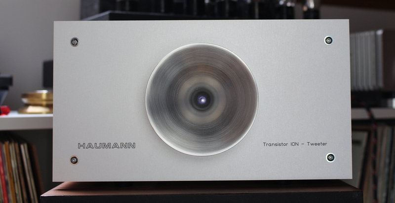
Transistor Ionophone
December 2020
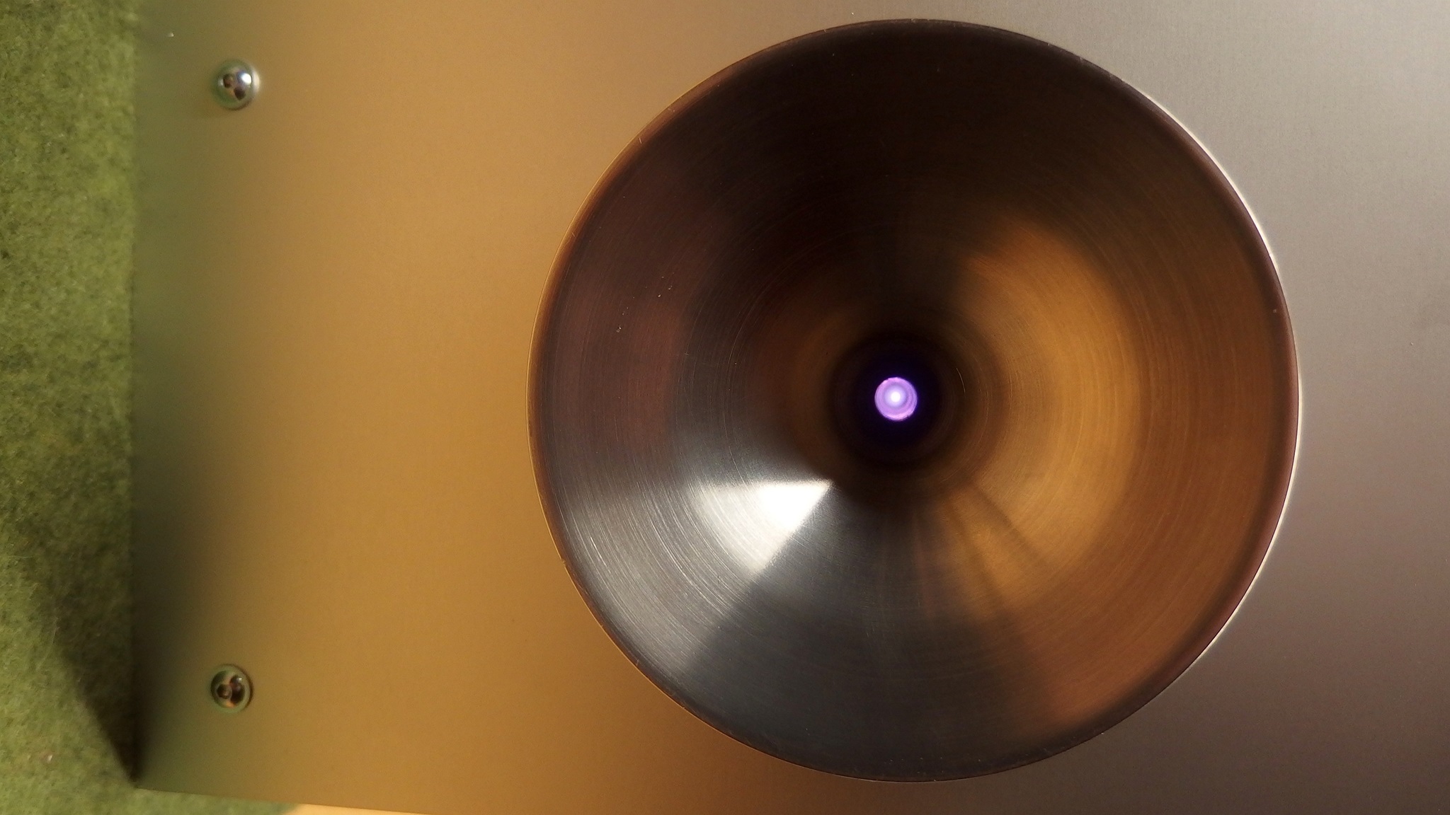
No Tube ? no high voltage ? Yes it works......
I want always build a full transistor Ionophone. Of course Magnat build a full transistor plasma tweeter, but this tweeter was omnidirectional without horn. I like the horn version because it is easier to integrate it in a conventional speaker and the horn has really sound preassure.
I think this is the world first full transistor Ionophone.
I will make a PCB in near future for this. At the moment we are in christmas preparation and time is a rare thing.
Also my free Eagle Version only allow 80mm x 100mm PCB. This circuit will be larger so I have to switch to an other programm. I hate it because I have to learn new with the other programm and things will go slow.
Anyway in January 2021 I will try to create new PCB's and publish the details so that it will be availible for the DIY community.
In the meantime enjoy the little Video beside.
Update Jan 2021
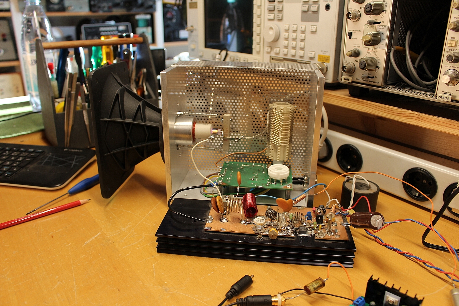
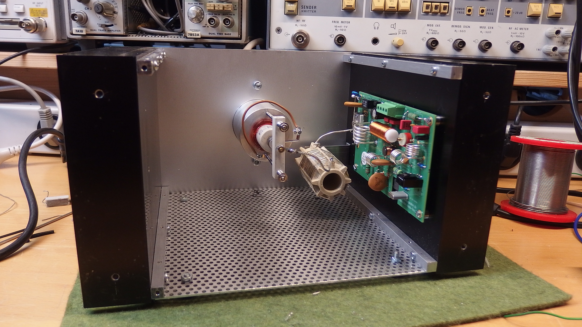
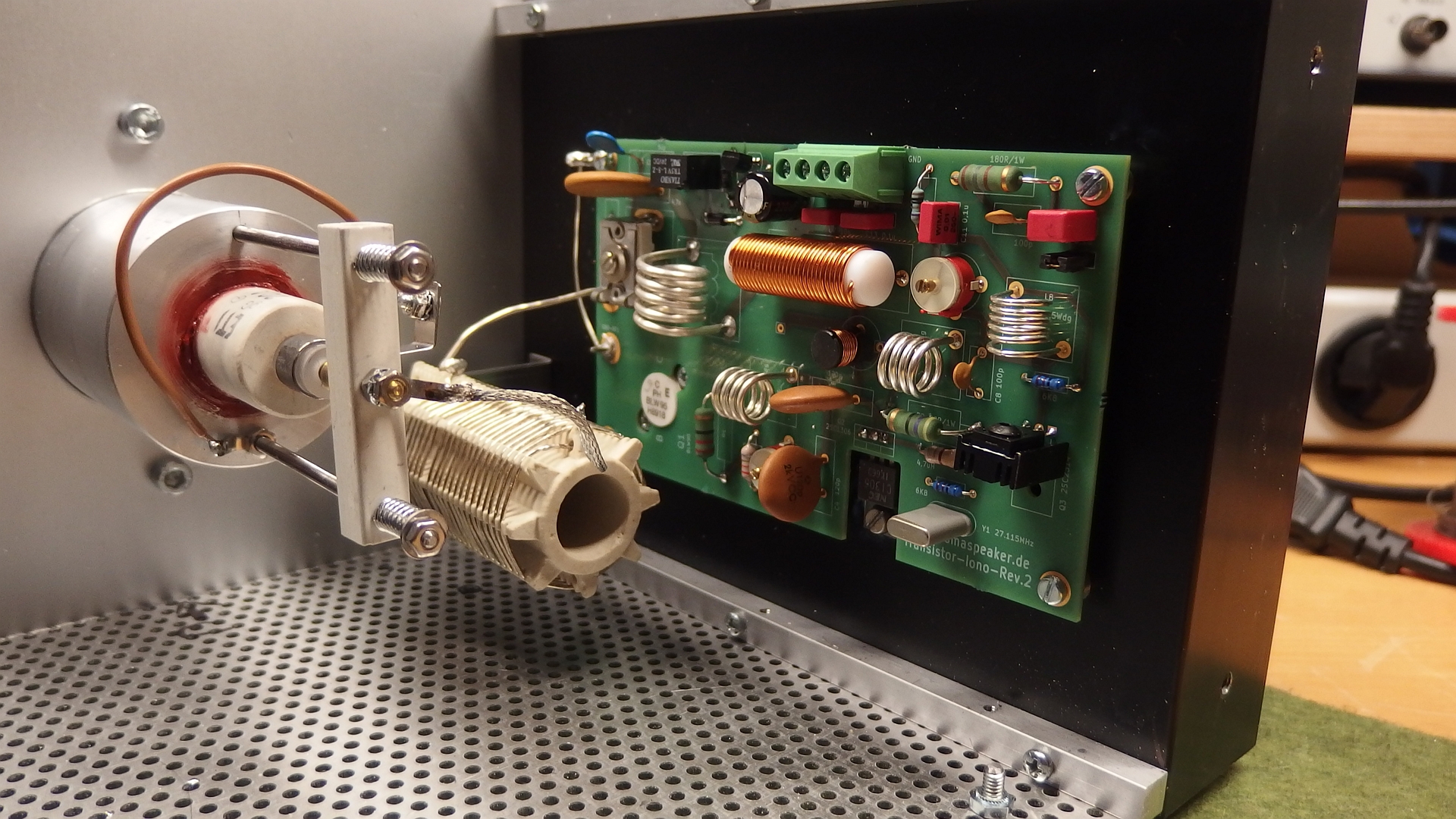
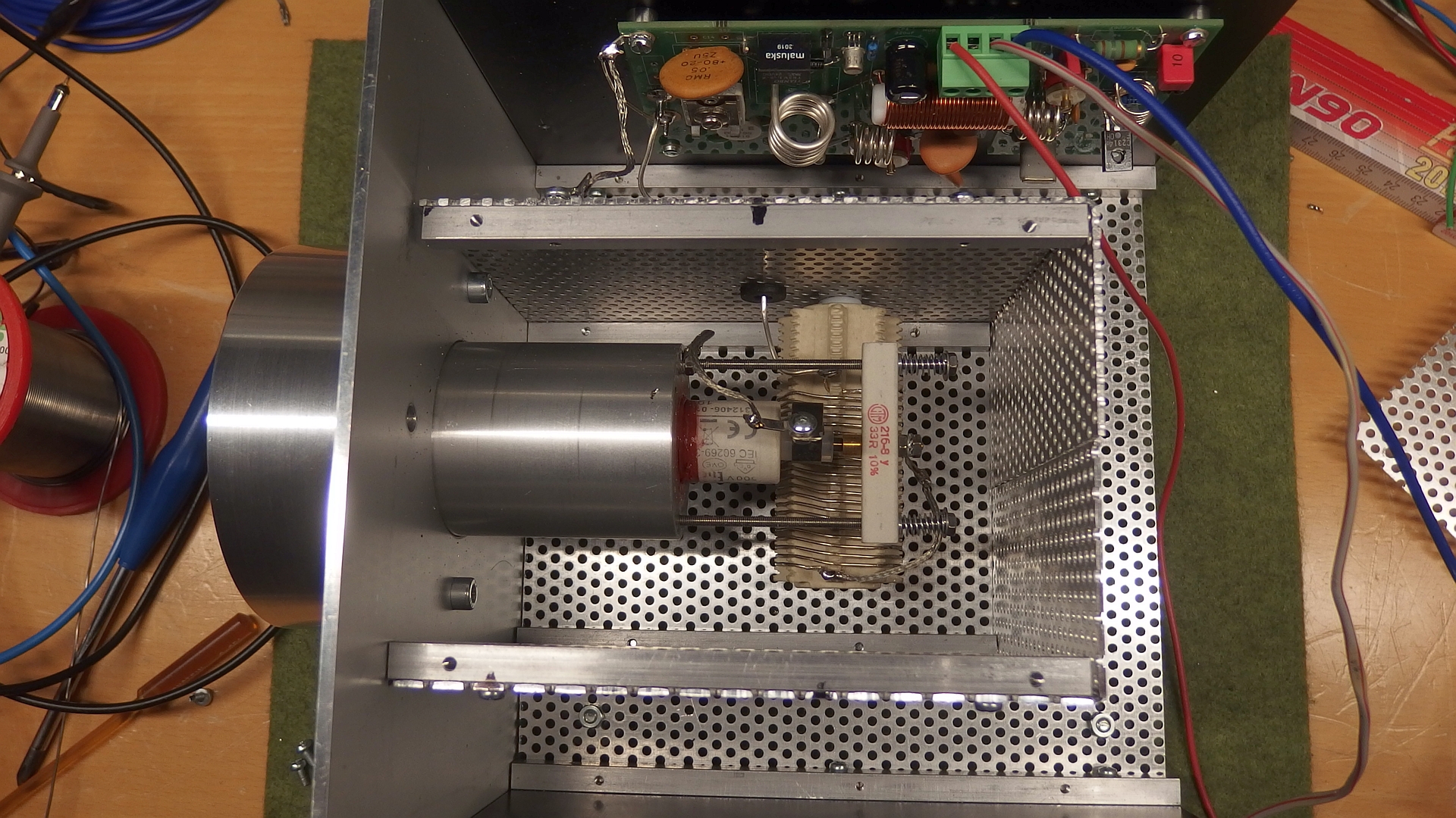
Now the Printed Circuit Board for the RF-Part and the mechanical parts for the first prototype are finished.
The circuit worked directly but there were some difficulties with the adjustment. With RF you never know how it comes out. Shielding is a very important factor. The original design with the Tube is easier because it is a self oscillating device. That means the frequency is free running and you dont need adjustment. The solid state design has a fixed frequency at 27MHz so I have to adjust the whole circuit. If you for example change the coil placement you have to adjust the circuit new. Also the hight power RF in the cage confused the Audio Amplifier so I had to shield the loading coil and the plasma cell.
Audio Amplifier
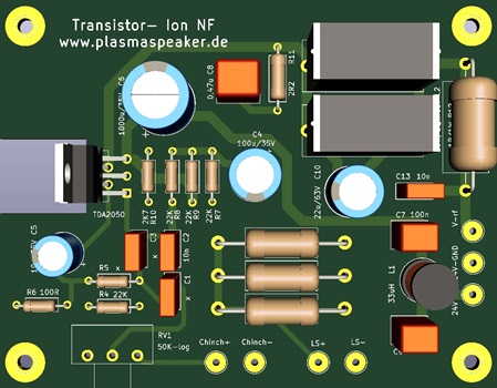
In the last weeks I finished the development of the Audio Amplifier. I use a TDA2050. The integrated device ist a perfect amplifier. It can amplify up to 80Khz which is more than enough for the tweeter. Also the output power match the RF part well.
I build in a 12db high pass filter which can be used or bypassed. The crossover frequency can be changed with two caps between 2,5 kHz to 3,5kHz without changing resistors.
In my current setup I have bypassed the filter because I am using a external one. The amplifier has a chinch input 0,775V impedance 10Kohm and a speaker input 8 Ohm. The device has a volume knob for easy matching in loudness. It need also 24V as the RF part so only one power supply is needed.
Update Feb. 2021
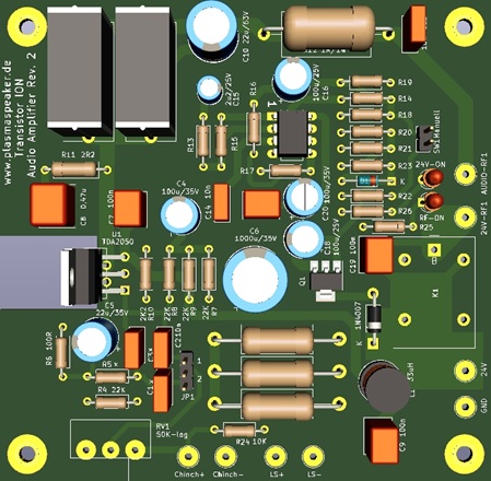
The Tweeter has now a automatic power on circuit. When audio signal is detected the tweeter turns on automaticly. If the Audiosignal is absent for apr. 6 minutes the tweeter turns off. This is really convenient you don't have to go to your speakers to turn them on. In the "off" mode the power consumption is apr. 0,01W (10mW stand by).
Power Supply
This is the easiest part of the whole thing. I use a simple Laptop 24V/5A switching power supply.
The circuit draws about 3A but you need "Headroom" because the efficiency of switching power supply's go down when they get warm.
Be aware there are cheap chinese power supply's on the market which have the minus of the 24V connected with the main earth. This have to be disconnected because you get grounding problems which might be result in "poping" noise in the speaker. I had one of them and was searching a half day until I find this out. Measure the minus of the 24V to the ground pin of the main connector with a continuity meter. When you have connection dont use it.
I found an other fault. There are also supply's which have enormous switching noise on the 24V DC line. Unfortunately the tweeter can reproduce it. My daughter heard this high frequency and then I measured it with the oscilloscope. It seems my ears getting old. I opened it and found that the output electrolytic cap had only 50% of the capacitance. I change it to low ESR Panasonic caps and the fault was gone.
Here a short Video how the combination performs
This Video is done with the internal mic of the camera, but you get the idea that this combination plays really good.
This is a two way system, plasmatweeter, KEF bass/midrange chasis B200 SP1054 and a KEF passiv radiator SP1042(insted of a reflex tunnel). Cross over is 3500Hz.